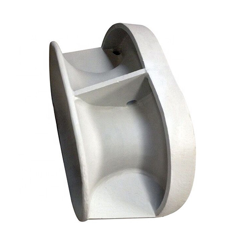
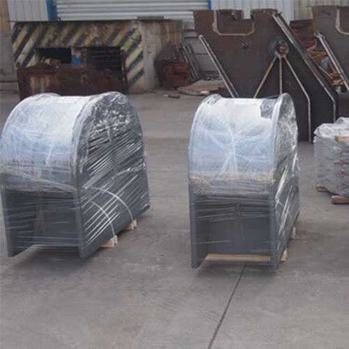
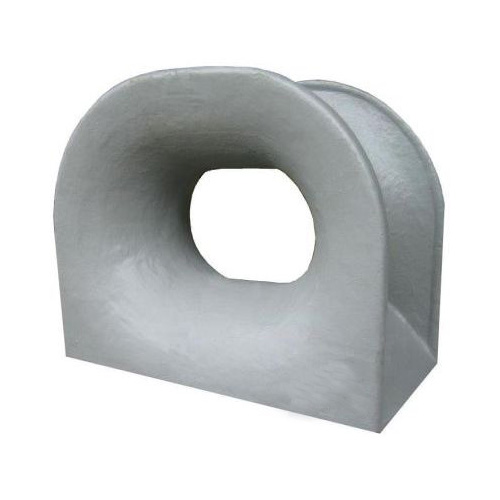
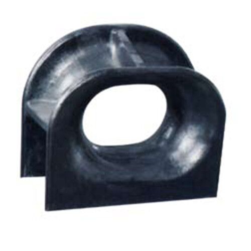
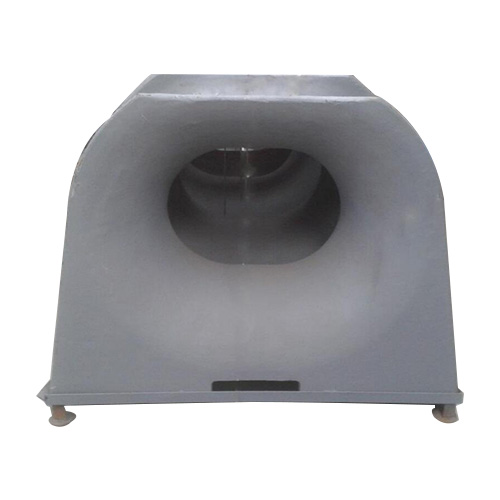
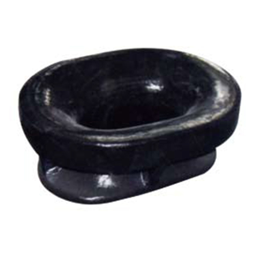
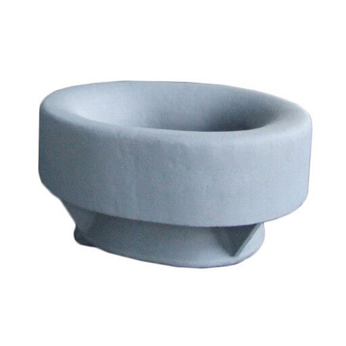
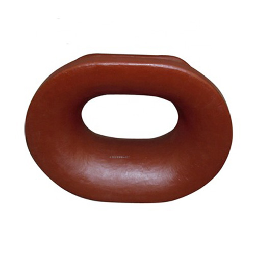
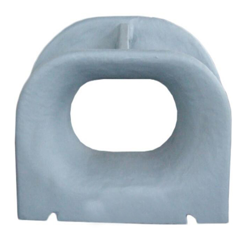
Bulwark mounted ISO13729 closed mooring chock is a special type of anchor hole at a vessel’s bow bulwarks. It is specially used to guide the mooring ropes of large ships. The closed chock is made of high quality cast steel and bolted or welded to the hull. It is used to lead the mooring and towing rope from the ship’s inboard to outboard.
As a large ship mooring chock, it meets the outfitting design by the requirement of Panama Chock. This closed chock is very important mooring equipment. In the process of mooring ship, it bears huge loads. The radius of the chock surface was designed based on the bending ratio of rope through the chock of not less than twelve times the wire rope diameter. Because this type of mooring chock is closed, the cable will not jump out.
As a professional marine equipment supplier, Boomarine provides a wide range size of ISO13729 closed chock to meet the requirements of different projects. Customers can choose the suitable ISO13729 closed chock according to the size of the vessel and the diameter of the pipeline. In addition, we can also provide a series of customized solutions. If you have any needs, please feel free to contact us
The chocks are classified by their installation site as follows:
- Type A – ISO 13729 deck mounted closed chock
- Type B – ISO 13729 bulwark mounted closed chock
Technical Requirements:
- All surfaces of the closed chocks including welding shall be free from any visible flaws or imperfections.
- All surfaces in contact with the ropes shall be free from surface roughness or irregularities likely to cause damage to the ropes by abrasion.
- The closed chocks shall be coated externally with an anti-corrosion protective finish.
Dimensions: (mm)
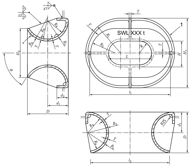
Dimensions and SWL of Type B – Bulwark-mounted closed chocks
| Nominal size (L × H × D) | l1 | l2 | H1 | H2 | R | R1 | R2 | R3 | R4 | R5 | ||
| 250x200x214 | 516 | 441 | 466 | 306 | 100 | 233 | 153 | 108 | 96 | 150 | ||
| 300x250x286 | 638 | 554 | 588 | 410 | 125 | 294 | 205 | 144 | 128 | 180 | ||
| 350x250x333 | 736 | 646 | 636 | 449 | 125 | 318 | 224.5 | 168 | 150 | 200 | ||
| 400x250x381 | 834 | 736 | 684 | 450 | 125 | 342 | 225 | 192 | 172 | 250 | ||
| 450x250x381 | 884 | 786 | 684 | 450 | 125 | 342 | 225 | 192 | 172 | 250 | ||
| 500x250x381 | 934 | 836 | 684 | 450 | 125 | 342 | 225 | 192 | 172 | 250 | ||
| 400x250x428 | 882 | 778 | 732 | 515 | 125 | 366 | 257.5 | 216 | 194 | 250 | ||
| 450x250x428 | 932 | 828 | 732 | 515 | 125 | 366 | 257.5 | 216 | 194 | 250 | ||
| 500x250x428 | 982 | 878 | 732 | 515 | 125 | 366 | 257.5 | 216 | 194 | 250 | ||
| 500x400x428 | 982 | 878 | 882 | 665 | 200 | 441 | 332.5 | 216 | 194 | 250 | ||
| 500x250x525A | 1078 | 976 | 828 | 551 | 125 | 414 | 275.5 | 264 | 240 | 320 | ||
| 500x400x525A | 1.078 | 978 | 978 | 701 | 200 | 489 | 350.6 | 264 | 240 | 320 | ||
| 500x250x525B | 1078 | 976 | 828 | 554 | 125 | 414 | 277 | 264 | 238 | 320 | ||
| 500x400x525B | 1078 | 978 | 978 | 704 | 200 | 489 | 352 | 264 | 238 | 320 | ||
| Nominal size (L × H × D) | R6 | d1 | d2 | T | θ | Welding leg lengtha | SWLb | Wire rope diameterc (recommended) | Calculated weightd (kg) | |||
| z1 | z2 | (kN) | (t) | |||||||||
| 250x200x214 | 138 | 108 | 80 | 12 | 44° | 6 | 5 | 226 | 23 | 18 | 49 | |
| 300x250x286 | 164 | 144 | 100 | 16 | 44° | 8 | 65 | 422 | 43 | 24 | 100 | |
| 350x250x333 | 182 | 168 | 120 | 18 | 55° | 9 | 7 | 549 | 56 | 28 | 141 | |
| 400x250x381 | 230 | 192 | 120 | 20 | 47° | 10 | 8 | 687 | 70 | 32 | 184 | |
| 450x250x381 | 230 | 192 | 120 | 20 | 47° | 10 | 8 | 706 | 72 | 32 | 194 | |
| 500x250x381 | 230 | 192 | 120 | 20 | 47° | 10 | 8 | 765 | 78 | 32 | 202 | |
| 400x250x428 | 228 | 216 | 120 | 22 | 56° | 10 | 9 | 883 | 90 | 36 | 264 | |
| 450x250x428 | 228 | 216 | 120 | 22 | 56° | 10 | 9 | 912 | 93 | 36 | 276 | |
| 500x250x428 | 228 | 216 | 120 | 22 | 56° | 10 | 9 | 932 | 95 | 36 | 288 | |
| 500x400x428 | 228 | 216 | 120 | 22 | 56° | 10 | 9 | 893 | 91 | 36 | 311 | |
| 500x250x525A | 296 | 264 | 120 | 24 | 53° | 10 | 95 | 1148 | 117 | 44 | 379 | |
| 500x400x525A | 296 | 264 | 120 | 24 | 53° | 10 | 95 | 1158 | 118 | 44 | 408 | |
| 500x250x525B | 294 | 264 | 120 | 26 | 53° | 10 | 105 | 1413 | 144 | 44 | 405 | |
| 500x400x525B | 294 | 264 | 120 | 26 | 53° | 10 | 105 | 1383 | 141 | 44 | 442 | |
| a: The welding method may be changed based on the same welding volume/strength. b: The SWLs shown in this table are for reference only.These are based on the loadings as mentioned in Annex A. “SWL”may be adjusted depending on the actual loading conditions,and the actual marking shall be as agreed between the user and the manufacturer. c: The wire rope diameter (recommended)is only for reference based on bending ratio of rope through the chock of 12 times. d: The calculated weight is for relerence only. * Dimensions in millimetres | ||||||||||||
